
Project
Hardware
Gigatron Micro
V1.50 (c) 2018-2019 Joerg Wolfram
V1.50 (c) 2018-2019 Joerg Wolfram
1 Legal
The programs are subject to the BSD 2-Clause LicenseThe publication of this project is in the hope that it will be useful, but WITHOUT ANY WARRANTY, escpecially without the implied warranty of MERCHANTABILITY or of INABILIBILITY FOR A PARTICULAR PURPOSE.
The project was developed under Linux, a compatibility with other operating systems is not guaranteed. The provided binary files are OS independend.
All trademarks mentioned in the text are the property of their respective owners. This documentation is derived from the german original so there may be things which are not properly translated.
2 Wozu?
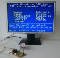
The project emulates a TTL-based single-board computer developed by Marcel van Kervinck and Walter Belgers( https://gigatron.io ).
The main reason, however, was the challenge of being able to program cycle-accurate on a modern 32-bit controller and to deal with ARM assembly code.
3 What will be amulated?
It emulates a gigatron with 64K RAM, the 'external' hardware is virtually identical to the original (except for the lower voltage levels). To achieve this, the controller is overclocked to 225 MHz and has with 36 clock cycles available to execute a gigatron command.Unfortunately, the emulation is not 100% because I had not achieved to detect the rising HSYNC edge for the I/O ports. But that could be compensated by small patches on the ROM image and two at this time unused commands. Insted of 0x18 (ld $dd,out) I use 0x1C for the rising edge of HSYNC and equivalent instead of 0x19 (ld [$dd],out) a unused commans at 0x1D. For the existing ROM images (v1-v3), the tool for the conversion into ASM source code also takes over immediately the patching with. The instruction code is written to the high byte of every word (byte swapping).
4 How the emulator works
The project is written entirely in ARM (thumb) assembler and does not use RAM (even a stack). All information will be kept in registers. The selected ROM image is copied to the RAM of the controller at startup and the CCM RAM is used as emulated RAM. The emulator itself runs from the flash (with prefetch enabled). There are 256 small 'program islands', which each execute a command and then jump to the 'program island' for the next command.Since the Instruction code is located in the high byte, can be easily by masking out the lower 8 bits and adding the start address determine the address of the next command. The lower 8 bits of Port A are used as the video port, bit A8 is SER_DATA. over Port C0-C7 LEDs and audio are controlled. In addition, there are two LEDs on PORT B5 and B7, they are used for debugging during development and are not actually necessary.
5 Select ROM Image
By default, the v3 ROM is loaded. If during the power-up sequence (until both status LED light up) the A button on the the game controller is pressed, the v1 ROM will be loaded instead. If the B button is pressed, the v2 ROM will be laoded.6 Compile the project
In the bin-folder there are a gtmicro.s39 file, which can directly flashed to a STM32F405. To translate the source code there is a makefile in the source directory, which still contains the path to the system ARM-NONE-EABI toolchain. Change this at Your need. The programming command (make prog) is adapted to my UPROG2 programmer.7 Changelog
Jan 7th, 2019 version 1.50- Initial public release
created with latex2web.pl v0.64 © 2006-2018 Joerg Wolfram